Skip to content
  • Home
  • Account
  • Restricted content
  • OBEX
  • Chips Tips
  • Logout
  • Shop
  • QuickBytes
Propeller OBEX
  • OBEX
  • Forum
Login
Propeller OBEX

Propeller 2

  • Configuring Visual Studio Code for Programming the P2 on Mac, Windows, and Linux
  • Breakout Board Options for P2 Edge Modules
  • Solar Panel Monitoring Demo (Intro to Using Video 3 of 3)
  • Wireless Programming with the ESP8266 WX Module
  • Brushless DC Motor Control Demo
  • Colorful Terminal Output with ANSI Escape Sequences
  • XBee RF Transparent and API Mode Demo
  • DS3231 Real Time Clock I2C Demo
  • Multiple Servo Control (up to 64) Object
  • Multiple Serial Port (8 UART – 16 Tx/Rx) Object
  • Goertzel Operation with Ultrasonic Transducers
  • Web Page Control of WS2811 LEDs Using the IoT Gateway on Raspberry Pi
  • 320×240 LCD Driver for ILI9341 Controller and XPT2046 Touch Screen
  • Digital Sample ADC to DAC + Analog Frequency to DAC
  • Using Smart Pins to Measure Frequency Output of TSL235R Light-to-Frequency Sensor
  • Ping))) Ultrasonic Distance Sensor with Graphical Debug Demo
  • Simple Analog Input
  • P2 Edge 16 MB Flash Reader and Explorer Utility
  • LED Matrix used as an I/O Test Utility
  • Arlo Conversion to P2 with the Universal Motor Controller
  • Five Buttons On One Pin
  • P2 RTC Add-on Board Demo
  • Simple Video Driver – Using Images (Intro to Using Video 2 of 3)
  • Starting Your P2 Project with a Spin2 Template
  • E-Ink Display Demo
  • MAX7219 LED Display SPI Demo
  • DHT11, DHT22, CM2302 Humidity and Temperature Sensor Object
  • NMEA GPS String Parsing
  • Floating Point Math: DEBUG and Terminal Display Example
  • LEDs – Beyond the Basics
  • Quadrature Encoder Object
  • P2 RTC Add-on with GPS Module
  • DVI/VGA Text Driver Demo
  • PCF8574 I2C LCD Demo
  • Simple Sound Engine Demo
  • 1-Wire Driver with DS18B20 Temperature Sensor Demo
  • Send Email from the Propeller 2 Using the IoT Gateway on Raspberry Pi
  • I2C Device Bus Scanner Utility
  • 32-Channel ADC Object
  • Tetris
  • Video Hardware with Character Map Demo (Intro to Using Video 1 of 3)
  • WS2811, WS2812, WS2812b, WS2813, SK6812x NeoPixel Object
View Categories
  • Home
  • Docs
  • Quick Bytes
  • Propeller 2
  • Five Buttons On One Pin

Five Buttons On One Pin

Reading Time: 1 min read

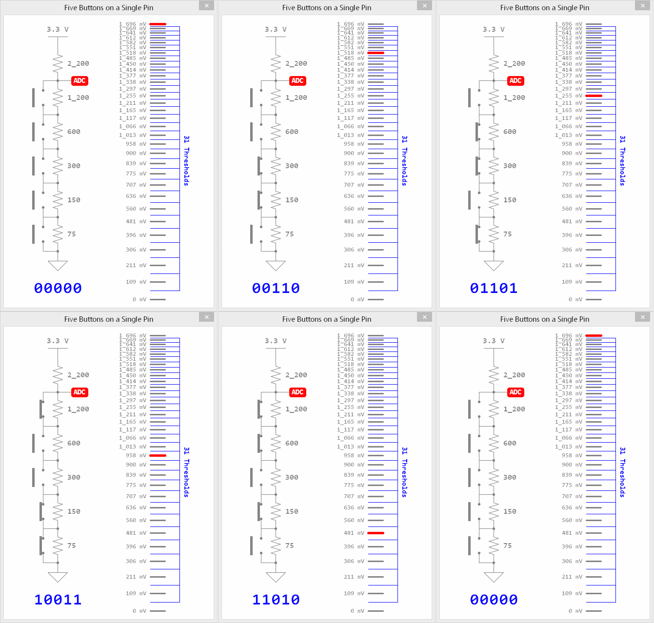
Schematic image is an animated gif of five pushbuttons being pressed in random sequences with a 5-bit binary pattern of numbers on the bottom. The image is generated from Propeller 2 debug statements that create a live visual graph, chart, or schematic from Propeller Tool. To wire this circuit, connect a 2.2K ohm resistor to 3.3V, then, with the resistors across the contacts of each button, a pushbutton with a 1.2K ohm resistor, a pushbutton with a 600 ohm resistor, a pushbutton with a 300 ohm resistor, a pushbutton with a 150 ohm resistor, and a pushbutton with a 75 ohm resistor, and then to ground. The schematic is vertically built with the 3.3V on top, ground on bottom. The buttons are actively moving up and down and the image was likely recorded with screen capture software watching Propeller Tool debug windows.

Description #

This program demonstrates how to series-connect five pushbuttons over one I/O pin, so that they can all be read in parallel by taking an ADC measurement and scanning a threshold table to determine their binary pattern. The program includes automatic debounce, too.

This may be accomplished with two resistor values: (5) 150 ohm and (5) 1.2K ohm with 1% tolerance like this:

  • Two (2) 1.2K ohm in series for the 2.4K ohm (this is an acceptable substitute for the 2.2K ohm value)
  • One (1) 1.2K ohm for the 1.2K ohm 
  • Two (2) 1.2K ohm in parallel for the 600 ohm
  • Two (2) 150 ohm in series for the 300 ohm
  • One (1) 150 ohm for the 150 ohm
  • Two (2) 150 ohm in parallel for the 75 ohm value.   

Parallax will offer these resistors and five pushbuttons in a bag for those who wish to prototype with this circuit. Expected release date early March, 2021. 

Compile with DEBUG to run this program. The DEBUG features create the graphic shown above from the Propeller Tool software and simulate what you’ll observe when you build the circuit and press the buttons in any possible combination. 

Parts Used #
  • P2 Edge Module
  • P2 Edge Breadboard
  • (5) Pushbuttons
Source Code #
  • Five_Buttons_One_Pin.spin2
Programming Language #
  • Spin 2
  • PASM2
Tools and Operating System #
  • PNut IVersion 0.35 or higher)
  • Propeller Tool for Windows (Version 2.5.0 or higher)
Additional Resources #
  • Propeller 2 Spin Documentation
  • Propeller 2 Live Forum Video: Simple Analog Input
  • Graphical Debug Tools in Spin2
  • Multpile Pushbuttons on One Pin Using Adaptive ADC (P2 forum thread)
Document Author #
  • Chip Gracey
Source Code Author #
  • Chip Gracey
Was this useful ?

Share This Article :

  • Facebook
  • X
  • LinkedIn
Still stuck? How can we help?

Still stuck? How can we help?

Updated on September 29, 2026
Arlo Conversion to P2 with the Universal Motor ControllerP2 RTC Add-on Board Demo
Table of Contents
  • Description
  • Parts Used
  • Source Code
  • Programming Language
  • Tools and Operating System
  • Additional Resources
  • Document Author
  • Source Code Author

Copyright © 2026 - Parallax Inc.
599 Menlo Drive | Rocklin, CA 95765 | USA