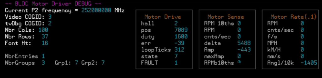
This P2 Quick Byte demonstrates the use of the 24V 4000 RPM BLDC Motor (featured in the September 2022 “Propeller 2 Mystery Box”) but it is also compatible with the 6.5″ Hub Motors.
Description #
The 4-channel Universal Motor Controller add-on (#64010) for the Propeller 2 Multicore Microcontroller can control DC, stepper, three-phase, or four-phase brushless (BLDC) motors. It also includes a feedback header, typically used for encoder or hall sensor signals from the motor.
This demonstration shows how to use a three-phase brushless motor with the 4-channel Universal Motor Controller, and how to simultaneously display live data, including current sense, channel voltages, speed and hall sensor feedback, to an HDMI monitor.
The video shows how to connect together the parts required to run the example source code, which was provided by Stephen Moraco at Ironsheep. The source code for this specific example is provided below, but the very latest version of the code can also be found at the IronSheep GitHub repository.
All of the configuration options for the motor code mentioned in the video, and shown in the “isp_bldc_motor_userconfig.spin2” file, can be found here https://github.com/ironsheep/P2-BLDC-Motor-Control/blob/main/MOTOR_CHOICE.md
Also included with the sample code are interfaces to control single or dual motors over a standard serial connection (Raspberry Pi, Arduino, BASIC Stamp, etc) or using an RC radio transmitter.
With the largest development board, the 64020 P2 Edge Module Breadboard (not shown in the video), you could add up to 3 of the universal motor drivers and also the HDMI add-on board, allowing you to drive up to 6 DC motors or 4 three-phase brushless motors, and still view the live data on a monitor.
For help please feel free to ask your questions at the GitHub issues page or ideally for a wider audience of helpers at our https://forums.parallax.com
These motors are ideal for testing proof of concept, developing code, or attaching to a small robotic platform.
The Hall sensor cables coming from the motor are color coded to match the corresponding motor phase cables. For this motor (Parallax 750-90020): U is yellow, V is blue and W is green. The Hall sensor has two additional cables: 5V is red, GND (Ground) is black.
The photo shows the color order at my homemade hall connector, starting at the 5V pin: red-yellow-blue-green-black.
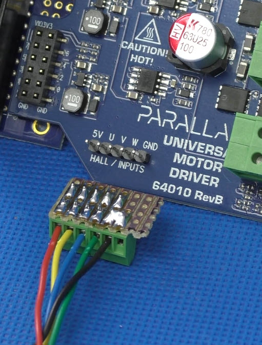
To make the homemade hall connector I used a scrap of 0.1” veroboard, a 5-way 0.1” female socket (PPPC051LFBN-RC), some 0.1” screw terminal blocks (enough to cover 5 positions, although I used 6 as that was available; OSTVN05A150). There are other ways to achieve this connection.
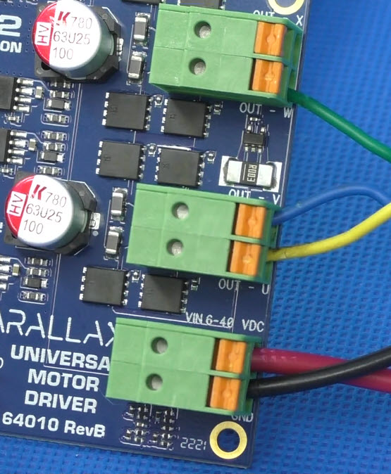
The spring terminals accept stripped cables with cross-section 0.2 mm² – 4 mm² (AWG : 24–12). Connect GND and VDC to your power source. Connect U, V, W, X to your motor phases.
In this example, we used a 12V battery as the power source, installed a 3 Amp fuse at the battery positive terminal, then connected the other side of the fuse to the motor driver VDC terminal. The motor driver GND terminal is connected directly to the battery negative terminal. It is ALWAYS necessary to include a fuse when powering from a battery pack (or any other power source) that does not have built-in overcurrent protection.
For the motor connections, we used 3 of the 4 available motor driver channels, and connected them with these colors: U is yellow, V is blue and W is green. The X channel spring terminal was left unconnected.
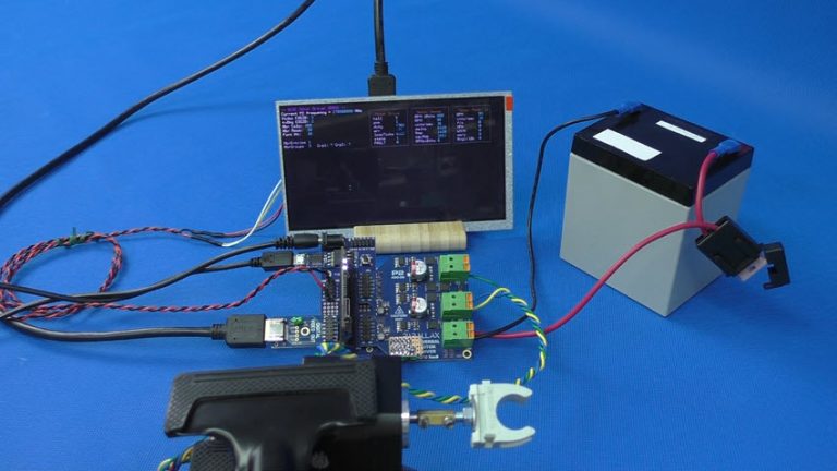
Parts Used #
- P2 Edge Module
- P2 Edge Mini Breakout Board
- Motor, BLDC, 24V, 4000 RPM
- USB Mains Adapter, 18W, 5V, 3A
- P2 Eval Digital Video Out Add-on Board
- 7" HDMI Display, 800 x 480
- Universal Motor Driver P2 Add-on Board
- USB A to DC 2.1mm Jack Cable
- USB A to Micro B Cable
- HDMI A Male to A Male Cable


