Description #
This Quick Byte includes three spin2 code archives and objects for using Digi XBee Modules in transparent or API packet modes of wireless communication between two Propeller 2 (P2) microcontrollers. Because the P2 may send and receive to itself, the example uses only one P2 Edge Module.
- For 01_xbee_transparent – Archive.zip we configure two XBee Series 3 Modules (802.15.4 XBee modules are fine too) with X-CTU for point-to-point communication in transparent mode (as a serial line over radio frequencies).
- The 02_xbee_at_reader – Archive.zip is a short example to configure an XBee module for API mode and read the configuration settings back for display in Parallax Serial Terminal.
- The 03_xbee_remote_node – Archive.zip shows how X-CTU software can send base station commands in API mode to a XBee module configured with a specific address. The archive includes an XML file with properly formatted commands.
Since this is a fairly long Quick Byte, you may wish to scroll to the bottom and review the parts used and download the source code before getting started. The entire Quick Byte and all three code archives are supported by the video presentation from Jon McPhalen, linked above. The video is a necessary companion if you wish to fully understand the capabilities of the example code.
TRANSPARENT MODE DEMO (01_xbee_transparent – Archive.zip)
Step 1: Configure the XBee Series 3 Modules for Transparent Mode Using X-CTU
First, download and install X-CTU from Digi. Connect your XBee Series 3 Module into a XBee USB Adapter Board and open X-CTU.
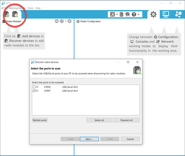
Choose the “Discover radio devices” button and select the COM port where the XBee USB Adapter is connected. Then click “Next” to set the port parameters.
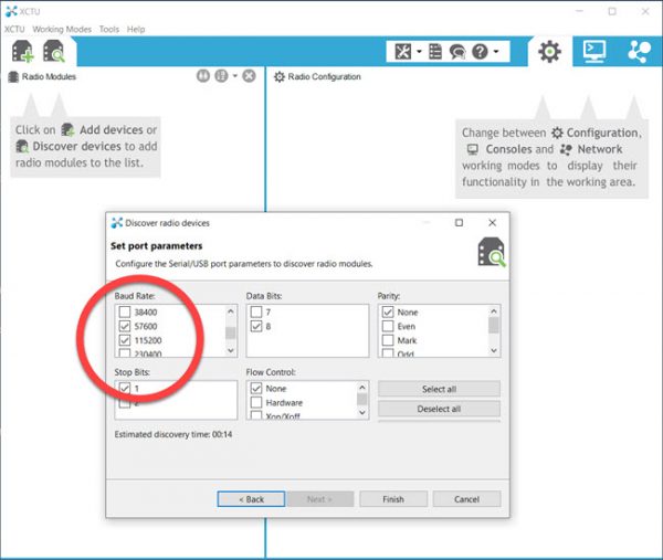
The default port parameters of 8 Data Bits, No Parity, 1 Stop Bit and No Flow Control are common. If you have previously configured the XBee Module to a particular baud rate, select that baud rate to discover the module again.
Click “Finish” to add the discovered XBee module.
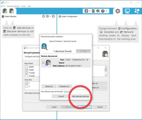
Choose “Add selected devices” to add the discovered XBee Module to X-CTU.
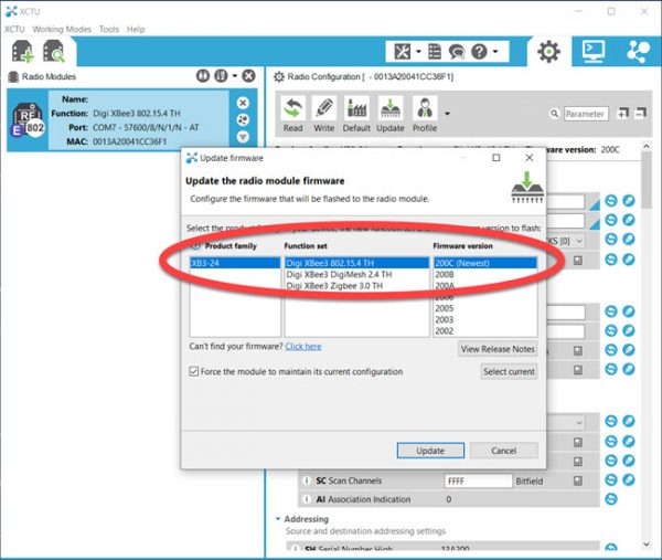
For this example, configure the XB3-24 as a Digi XBee 3 802.15.4 TH with the newest firmware and select “Update” to configure the firmware. The XBee Series 3 may be configured as a number of different prior models.
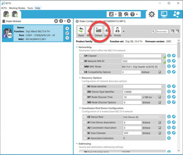
Next, we’ll clear any prior settings. Select “Default” and the module’s default settings will be applied.
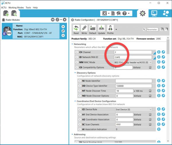
Set the CH Channel to “F” and ID Network PAN ID to “CAFE”.
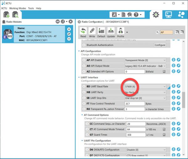
Set the BD UART Baud Rate to 57600.
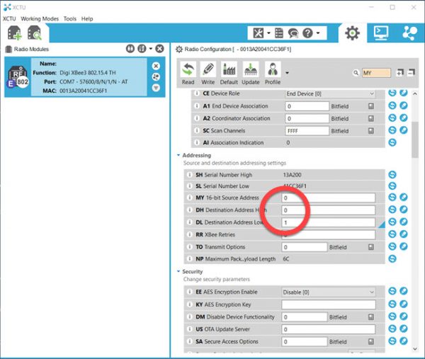
For the first module, set the address as follows:
MY 16-bit Source Address to 0
DH Destination Address High to 0
DL Destination Address Low to 1
Click “Write” to fully configure the first XBee Series 3 Module.
For the second module, follow all of the steps defined above but set the address as follows:
MY 16-bit Source Address to 1
DH Destination Address High to 0
DL Destination Address Low to 0
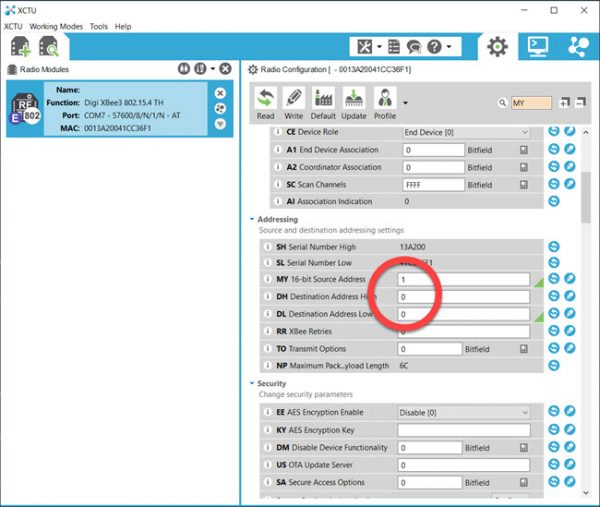
Click “Write” to fully configure the second XBee Series 3 Module.
Step 2: Install the Two XBee Series 3 Modules on a Propeller 2 Edge Breadboard
The source code defines the P2 I/O pins that are connected to the XBee. The I/O pins are defined as constants from the perspective of the P2. The XBee’s DOUT connects to the P2’s XB_RX1, and the XBee’s DIN connects to the P2’s XB_TX1.
The 01_xbee_transparent.spin2 source code makes this quite clear (but we point it out since it’s a common stumbling block):
con { app io pins }

  XB_RX1   = 33  { I }           ' connect to XBee DOUT
  XB_TX1   = 32  { O }           ' connect to XBee DIN

  XB_RX0   =  9  { I }           ' connect to XBee DOUT
  XB_TX0   =  8  { O }           ' connect to XBee DIN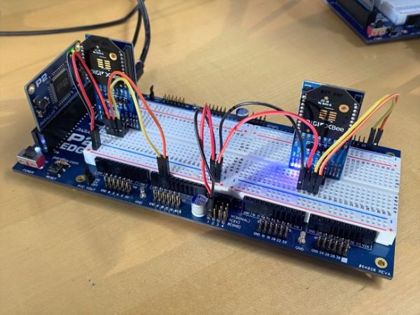
Step 3: Run the 01_xbee_transparent.spin2 Source Code
Then, open Parallax Serial Terminal and you will see the following as the two XBee modules communicate.
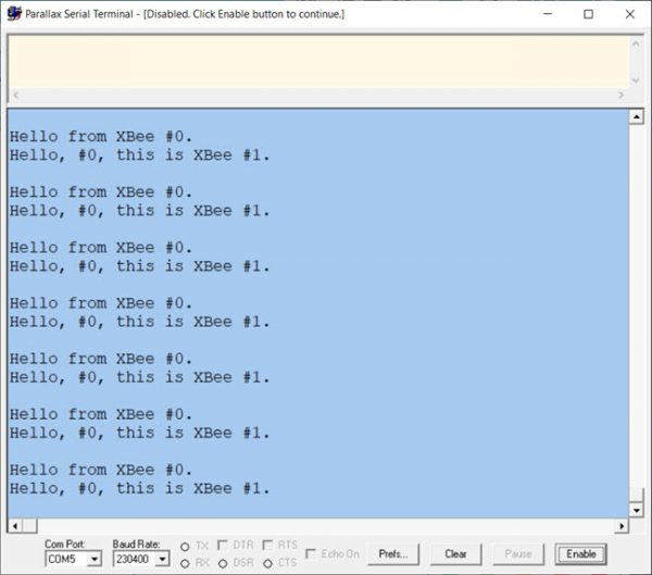
This example code may be used for point-to-point communication between XBee modules. The code archive includes a modifed version of the full duplex serial object epecifically for XBees.
API MODE READER DEMO (02_xbee_at_reader – Archive.zip)
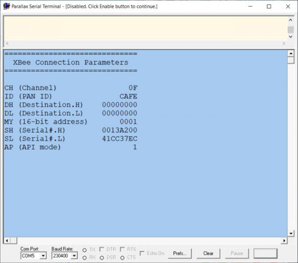
The API packet mode is configured with X-CTU and read back with the 02_xbee_at_reader.spin2 program.
Step 1: Configure the XBee Series 3 Modules for API Mode Using X-CTU
The process is similar to what is described above for transparent mode, except you will make two changes to the current configuration:
- Set the BD Baud Rate to 57,600
- Change the AP API Enable to API Mode Without Escapes (1)
- “Write” the updated settings to a module and return the XBee module to the P2 Edge Breadboard.
Step 2: Run the 02_xbee_at_reader.spin2 Source Code
Run the code example and open Parallax Serial Terminal. You may now observe the API mode settings.
XBEE API REMOTE NODE DEMO (03_xbee_remote_node – Archive.zip)
In this example, X-CTU is used to assemble an API packet to send to the XBee. Refer to the video to run this example.
Parts Used #
- P2 Edge Module
- P2 Edge Breadboard
- (1) XBee USB Adapter Board (#32400)
- (2) XBee XB3-24Z8PT-J Antenna (Low Current) Modules (#32421)
- (2) XBee SIP Adapter (#32402)


