Description #
This Spin2 example uses a technique known as Charlieplexing to verify that the pins on the P2 and its associated circuit traces on the host board are functioning correctly. In a typical LED blink example, a single general-purpose input/output (GPIO) pin is used to drive/power/light a single load/device/LED. The LED is both a device and a load. A load is simply any device that consumes power.
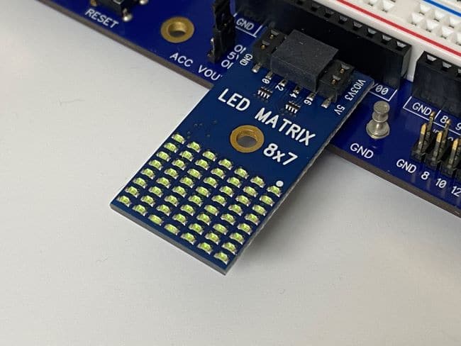
Charlieplexing is a technique allowing more LEDs to be powered with fewer pins based on the formula, p^2-p, where p is pins and is greater than 2. Why greater than 2? The proof is left for the student. For example, with three pins you can control six LEDs [3^2-3]. With the eight GPIO pins in a single 2×6 pin block on the P2 Edge Mini Breakout Board, you can power 56 LEDs. The P2 Eval LED Matrix Add-on Board has an 8×7 matrix of 56 LEDs. How is this possible? The answer is in the schematic for the P2 Eval LED Matrix Add-on Board, which shows how the 56 LEDs are Charlieplexed together.
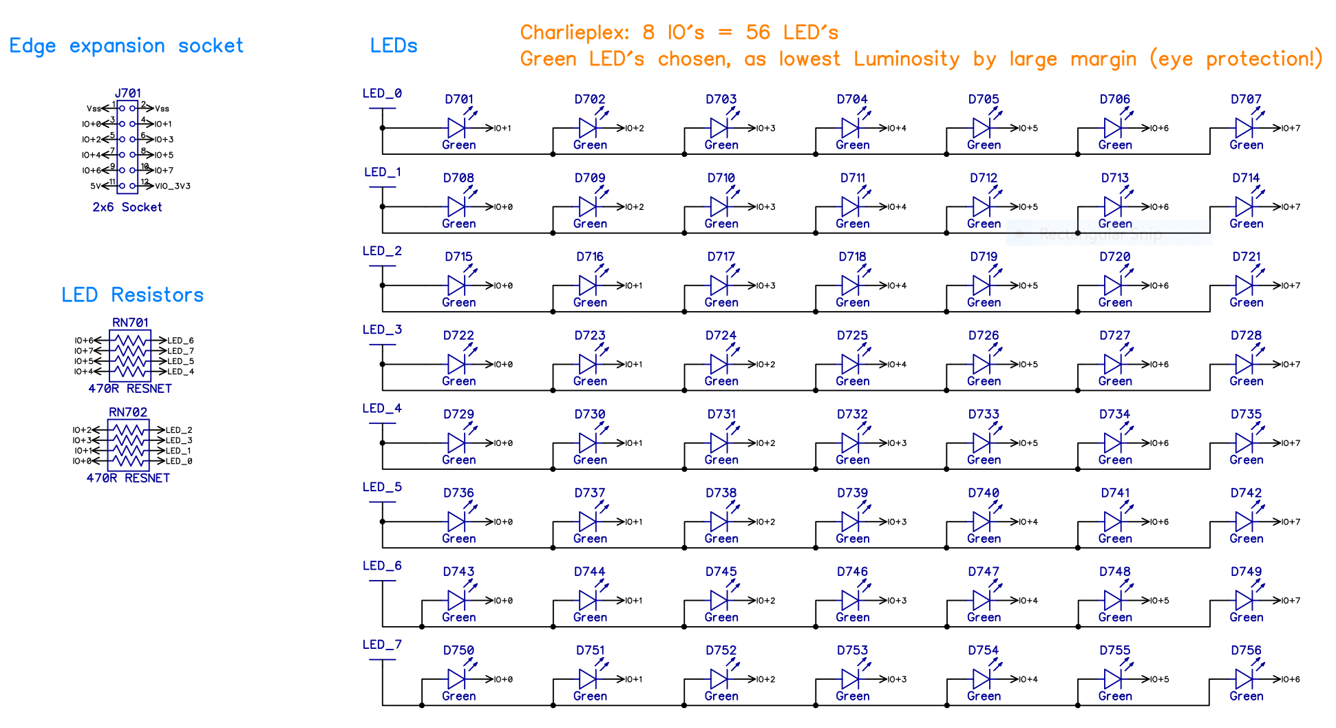
The truth is that only 1 LED can be powered at a time. How do you light all or a portion of the LEDs simultaneously? Charlieplexing takes advantage of a weakness of the human eye known as Persistence of Vision (POV). It is a condition where the eye continues to see a light source for a short time after the light source has been turned off. Televisions use this illusion as well. By switching each LED on and then off one at a time it is possible to create the illusion that all the LEDs are on at the same time. Any pattern can be displayed on the 8×7 matrix using this technique. This application creates the illusion that all the LEDs are lit simultaneously by switching each LED on and off in a sequence extremely fast. The hypothesis is if there is a problem somewhere in the hardware, one or more of the LEDs will not light. Assuming you have not introduced a bug (i.e., error) into the software. The variable, onDuration, controls how many microseconds each LED is held “on” before being switched “off” and moving to the next LED in the sequence. Reducing this variable makes the matrix appear “dimmer”. Increasing this variable makes the matrix appear “brighter”, however, there will be a point where the LEDs in the matrix begin to flicker because you are not sequencing through all the LEDs fast enough to maintain the illusion.
CON

  basePin    =  56 'basepins are 0, 8, 16, 24, 32, 40, 48 and sometimes 56.  I couldn't help myself, AEIOU and sometimes Y.
  onDuration = 500 'For me, this gives the brightest matrix without flicker [at default clock frequency] (ie >500 flickers, <500 dimmer)
  pinField   = basePin ADDPINS 7 'Include 7 more sequential pins to the basePin
Instead of using an algorithm to determine which pin needs to be high and which pin needs to be low, I use a lookup table (LUT).
DAT

  lut BYTE $01,$02,$03,$04,$05,$06,$07,$10 'LED matrix lookup table per guide.
      BYTE $12,$13,$14,$15,$16,$17,$20,$21 'Rows are top (row 1) to bottom (row 7)
      BYTE $23,$24,$25,$26,$27,$30,$31,$32 'Columns are left (column 1) to right (column 8)
      BYTE $34,$35,$36,$37,$40,$41,$42,$43 'Most significate 4 bits of each byte is the pin number to use as the HIGH pin.
      BYTE $45,$46,$47,$50,$51,$52,$53,$54 'Least significate 4 bits of each byte is the pin number to use as the LOW pin.
      BYTE $56,$57,$60,$61,$62,$63,$64,$65 'Eight (8) pins can Charlieplex 56 LEDs.
      BYTE $67,$70,$71,$72,$73,$74,$75,$76 'For example, to light the LED at the row 1, column 1 position, pin 0 must be HIGH, pin 1 must be LOW, all other pins must be FLOAT(ing).
For each of the 56 bytes in the LUT table which represents the 56 LEDs on the board, the high nibble is the HIGH pin number and the low nibble is the LOW pin number needed to light that LED (i.e. PINH(HIGH) and PINL(LOW). These numbers range from 0 to 7 and must be added to a BASEPIN number to get the actual P2 pin number.
PUB go() | BYTE offset, BYTE hiPin, BYTE loPin

  PINF(pinField) 'floats all 8 pins connected to the 2x6 header beginning at the basePin

  repeat
    repeat offset from 0 to 55
      hiPin := basePin + lut[offset].[%00011_00100] 'bitfield for upper 4 bits or high nibble
      loPin := basePin + lut[offset].[%00011_00000] 'bitfield for lower 4 bits or low nibble
      PINH(hiPin)
      PINL(loPin)
      waitus(onDuration) 'The longer the LED is on, the brighter it will be.  If it is on too long, all LEDs will flicker.
      PINF(pinField)
I detected an anomaly on P63 on the two breakout boards while using this utility. Checkout the forum thread “Anomaly Found with LED Matrix Test Tool” (see link in Additional Resources below) on how this anomaly was resolved.
Parts Used #
Source Code #
Programming Language #
Tools and Operating System #
- Propeller Tool for Windows.


